Six everyday parts from the browser CAD editor I'm building
5 October 2026
I've been building a CAD editor for alpaco.it for about five weeks now. It isn't public yet. It runs in the browser, keeps a history of every step, and does the solid modelling on your own machine in WebAssembly, so nothing gets uploaded anywhere.
The last few posts were all fillets meeting corners. Fun to fix, but it's not why anyone opens CAD. Mostly you open it because you need a box. Or a bracket, or some other dull thing that none of the generators here happen to make.
So today I modelled six of those, each one from an empty document. Click a picture to see the part from four sides.
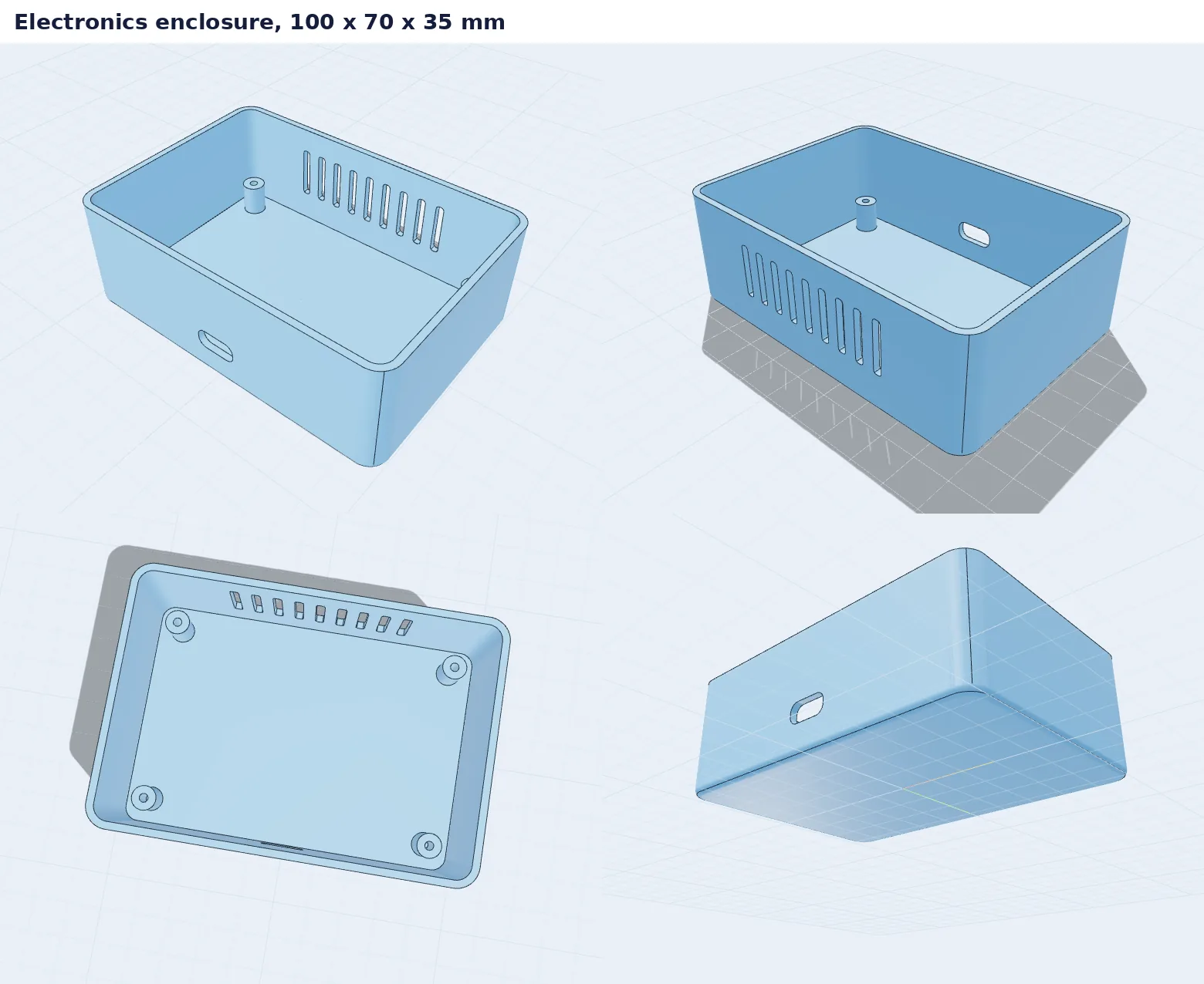 Electronics enclosure
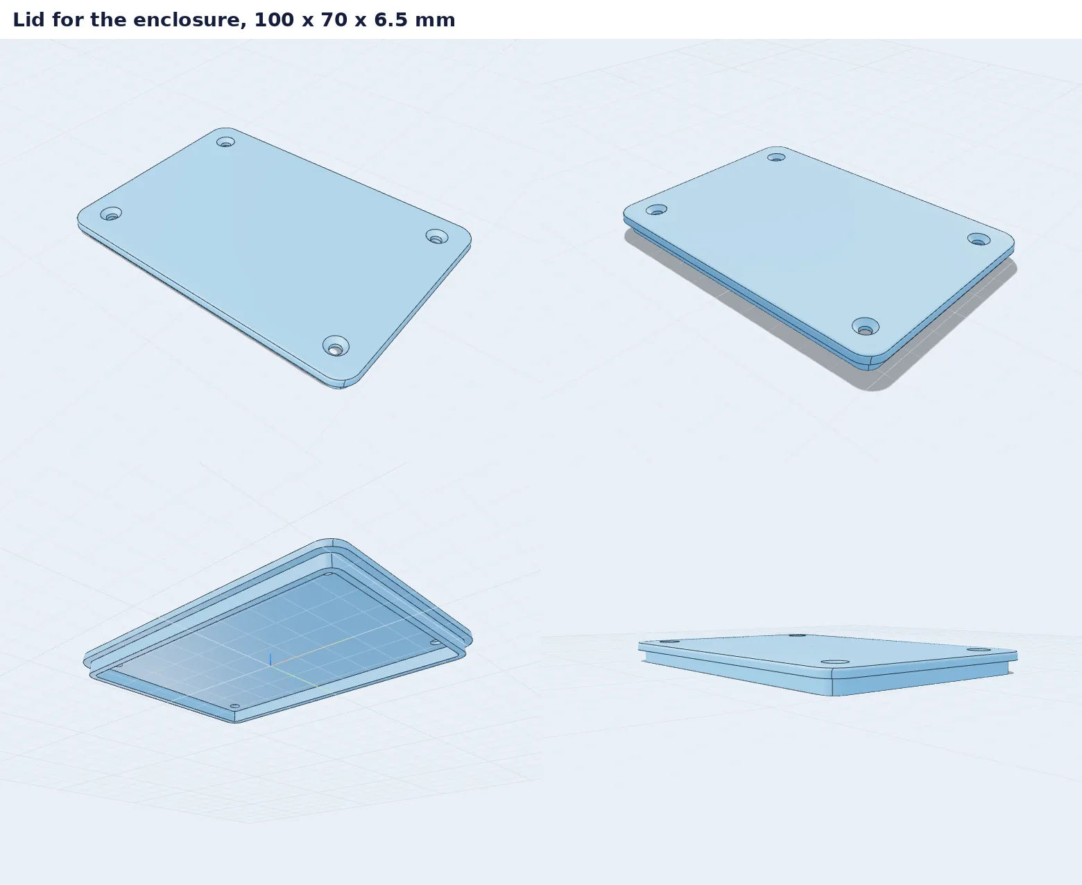 Lid with M3 countersinks
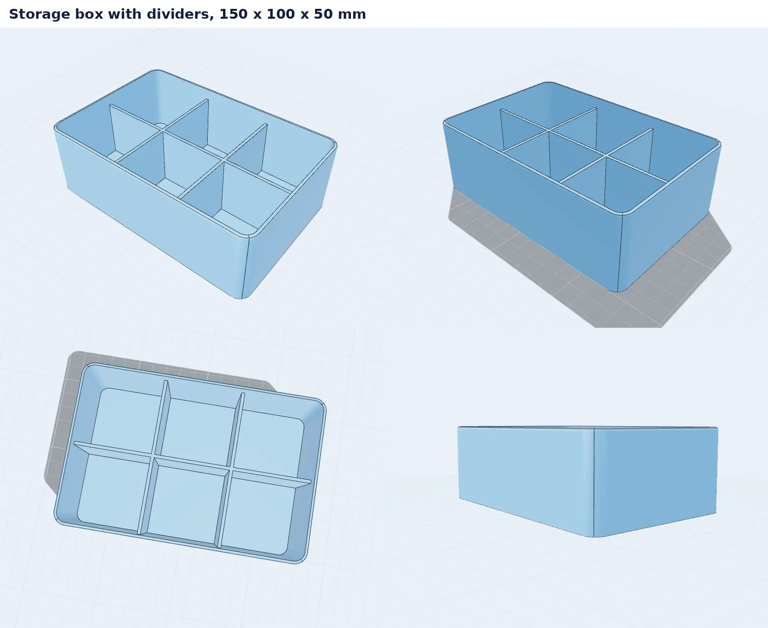 Storage box with dividers
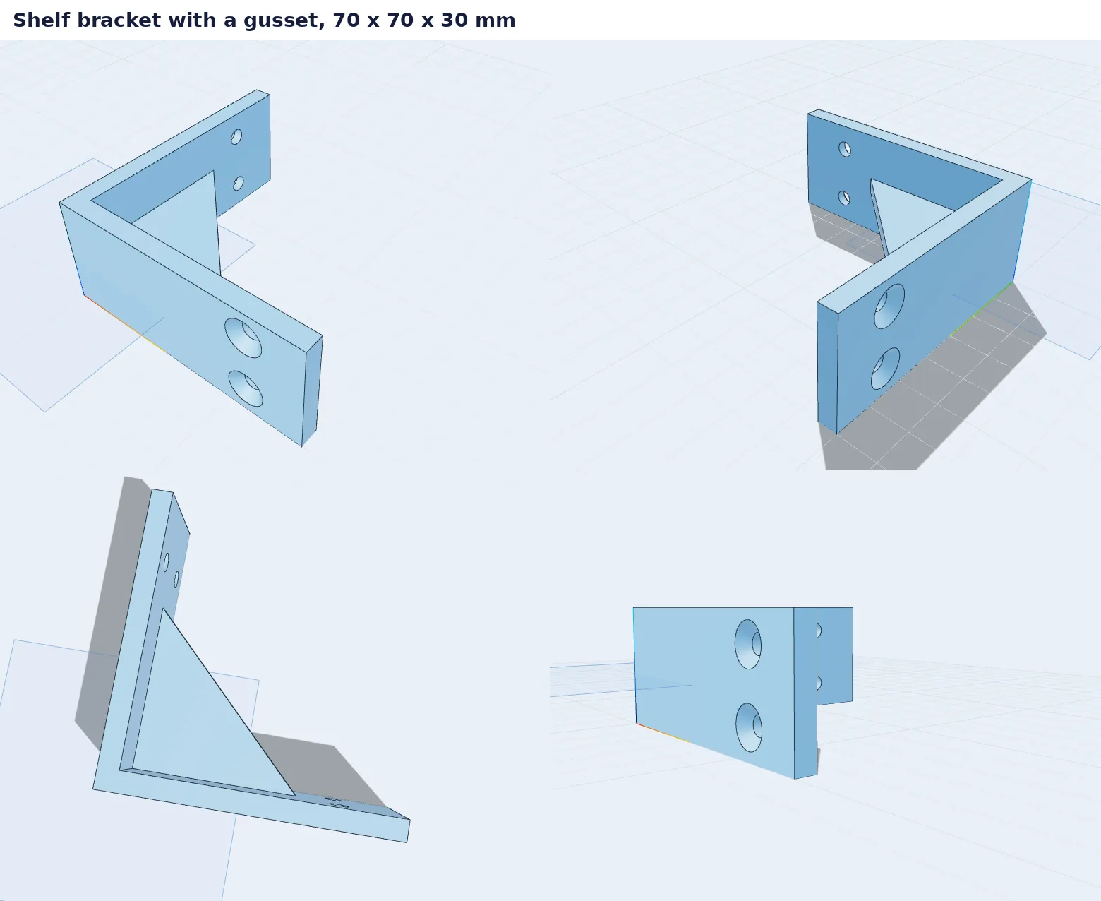 Shelf bracket
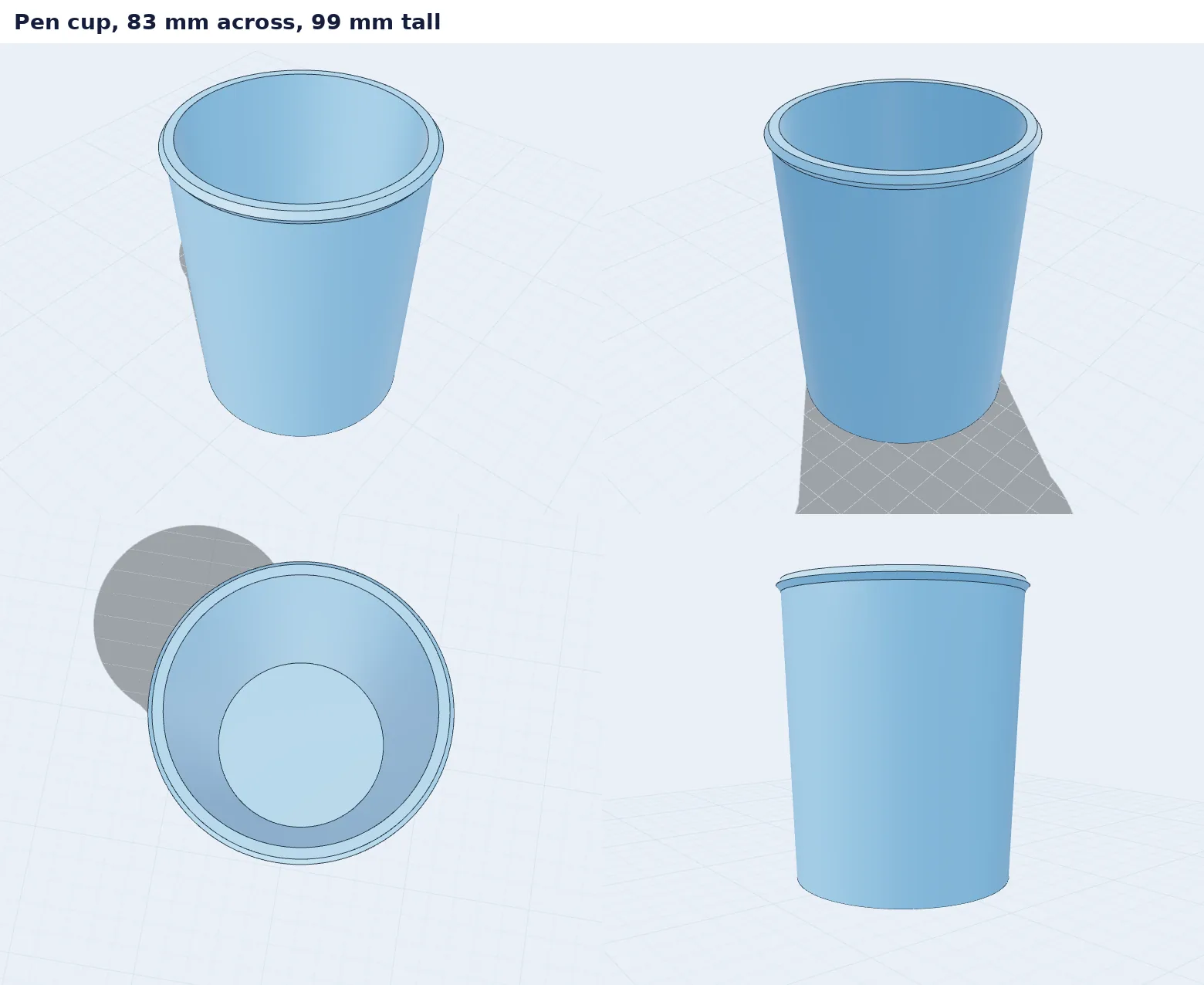 Pen cup
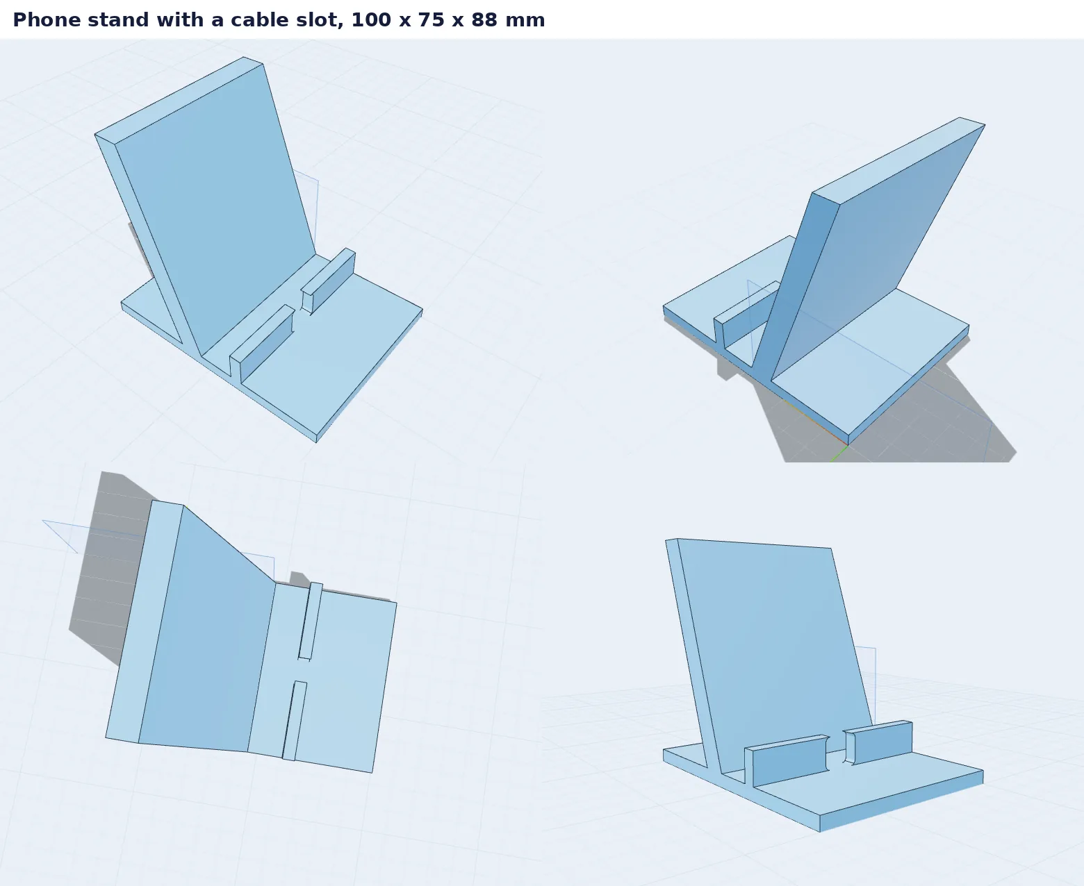 Phone stand
The six parts
The enclosure is the one I'd actually print. 100 x 70 x 35 mm, 2 mm walls, rounded along the bottom, four screw posts inside with 2.5 mm pilot holes, a USB-C opening at the front and nine vent slots at the back. 13 steps in the history. The lid goes with it. Its 4 mm lip drops inside the walls and the four countersunk M3 holes sit right over the posts.
The rest, quickly:
- a storage box, 150 x 100 x 50 mm, six compartments
- a shelf bracket, 70 x 70 x 30 mm, two countersunk M4 holes per leg and a 4 mm gusset that I sketched on a datum plane 13 mm off the bed
- a pen cup turned from one profile, 99 mm tall with a rolled lip
- a phone stand with the backrest at about 70 degrees and a slot in the front lip for the charging cable
Each one exports as a single closed body with no open edges, so there's nothing for the slicer to repair. The phone stand is the heaviest at 103 cm³. The lid is 19.7.
Where it went wrong
The vents. I drew one slot on the back wall and cut it 3 mm deep, a bit more than the 2 mm wall, on purpose. The editor flagged it, said the pocket was deeper than the material, and suggested ticking Through. So I ticked Through. Through goes through the whole part, which meant the slot crossed the empty box and came out of the front wall too. The USB opening did the same in the other direction. For a cut into a wall that warning shouldn't show up at all, and I'm changing it.
Then I patterned the slot, nine copies 6 mm apart, and four of them ended up in the air past the end of the wall. Turns out the back face's horizontal axis runs right to left when you look at it from outside. My first slot was at the wrong end. The editor did tell me four of the copies changed nothing, otherwise I'd have caught it much later.
I got the phone stand wrong twice in one go. I drew the profile flat on the bed, so the stand came out lying on its side (fine for printing, odd in a picture), and the backrest leaned forward instead of back. Your phone would have been resting on the underside of it. I redrew it on a vertical plane and flipped the lean.
The lid was my mistake, not the editor's. You can't start a hole on the base plane because there's nothing under it to drill into, so the lid is modelled the way it sits on the box, lip down, with the countersinks going in from the top.
Two things you can see in the pictures
In the views from underneath, the bed grid gets drawn over the part, so it looks like it's standing on glass. On the bracket and the stand there's also a thin blue outline of the datum plane that stays visible in the clean view. Neither shows up in the exported file.
Next
The Through warning first, then the grid. After that I want to build these six again with the mouse only, without typing a single number into the step list, and see how far I get.