A mount for any box and a window vent insert, two generators I built from Reddit threads
27 September 2026
I spent an evening reading r/functionalprint and r/minilab with one question: what do people model by hand, one at a time, when a set of numbers would do? Two answers came up again and again. A bracket that holds some box, a router or a power brick, under a desk. And a panel that fills the gap of a sliding window so a portable air conditioner hose can go through it. Three of the window threads had more than a thousand upvotes each.
Both are now generators: the Device Mount and Rack Panel Generator and the Window Vent Insert Generator.
A mount is a box plus clearance
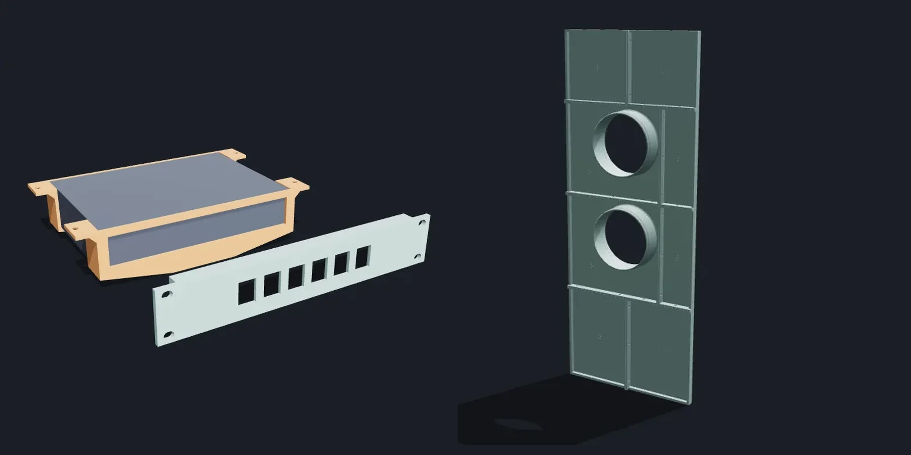
Every device is the same thing to the generator: width, depth and height, plus 0.5 mm of clearance. The rest is built around that box. For a router 180 by 130 by 38 mm, the default is two U-brackets, one over each end, the same part printed twice. Each is 219 mm wide and 28 mm long, with an M4 countersunk hole in each flange, and the pair comes to about 101 g of PLA.
Instead of brackets you can have two side rails the device slides into, which works for any width, or a full sleeve. Only the sleeve takes a VESA 75 or 100 plate, for a TV box behind the TV. An air gap puts standoffs under the device, for an amplifier that gets warm.
Every piece prints lying on its cross-section. The U, the flanges and the end stop are one profile pushed along the depth, so nothing overhangs and the layers wrap around the corners where the weight pulls. Screw holes that lie on the bed are teardrops. A floor wider than 60 mm gets thicker toward the middle. Flat strips sag.
Rack panels, 10 and 19 inch
The homelab threads asked for the same thing in a different shape. One person wrote that they had spent four weeks designing their 10 inch rack mounts. So the second half of the generator makes rack panels from 1 to 4 U: blank, with keystone ports, or with a cage for up to six identical devices.
The numbers come from the rack standard, and the README in every download lists where each one comes from. 1U is 44.45 mm and the panel is 0.8 mm shorter so two panels stacked don't jam. A 19 inch panel is 482.6 mm wide with holes 465.1 mm apart; a 10 inch panel is 254 mm with holes 236.5 mm apart. The holes are slotted 0.75 mm each way, because not every cheap rack is exact. Keystone openings are 14.97 by 19.45 mm with the panel thinned to 2 mm around them from behind, which is the thickness the latch on a keystone jack expects.
A 19 inch panel doesn't fit on a 256 mm bed. It comes in two pieces joined by glued dovetails in the plate, plus a bolted M3 splice bar across the top and bottom ribs. The dovetails keep it flat. The bars stop it folding at the joint.
A window panel in tiles
The window generator starts from the gap, measured with the window pushed open against the panel. The default is 240 by 900 mm with one 150 mm hose port. On a 256 mm bed that is four tiles and about 1.8 kg of PETG, joined by ribs on the room side with nine M4 bolts. The ribs also keep a 900 mm panel from bowing.
A port can be a spigot the hose slides over, a socket its cuff pushes into, or a rounded rectangle for the flat nozzle many air conditioners come with. Two ports can sit stacked or side by side for dual hose units. The cuts between tiles are placed row by row so no joint ever runs through a port. There is an optional bug mesh with openings of at least 1.2 mm, and a groove around the edge for foam tape, with a 45 degree roof so it prints without support.
Print it in PETG or ASA. Exhaust air from an air conditioner runs at 50 to 60 °C, and a window in the sun gets hotter than that.
What went wrong on the way
The first window panel with ribbed joints was not a closed solid. Two rib strips that met at a tile corner overlapped by a hair, and the mesh had edges shared by four faces instead of two. The ribs are now merged as flat shapes first and pushed up in one go. The foam-tape groove had the same problem at its corners.
The front view had a smaller bug. The tile holding the port drew its number half outside the tile, on top of the joint line, because the middle of the tile was the hole. The numbers now look for the largest free spot in their tile.
Two things I haven't checked with a print yet. The keystone opening is cut to the published size, but I haven't snapped a real jack into it. And the flat nozzle size, 190 by 70 mm by default, is my guess from photos, so the page asks you to measure yours.