I'm building a CAD editor in the browser
11 September 2026
The 37 generators on this site all work the same way: pick a model type, move sliders, download. That covers a lot, but every few days someone asks for a shape no generator makes. A bracket with one weird notch. A box with a slot in a side wall. For those you need real CAD, so for the last two weeks I have been building one. It runs entirely in the browser, no account, no upload, and the solid math happens on your machine in WebAssembly.
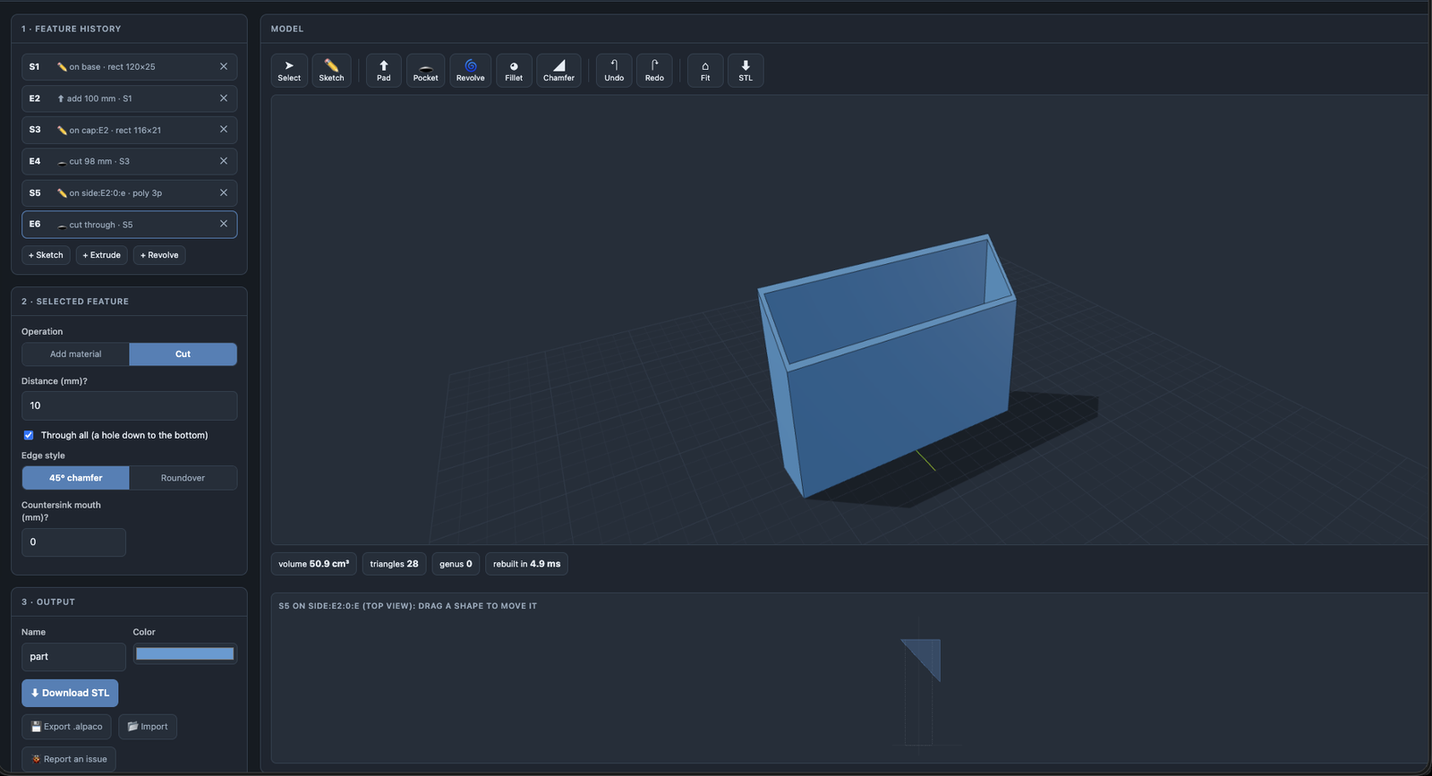
The screenshot above is a real part from the beta: a 60x40x100 mm shell with 2 mm walls and a triangular cut through the side. Six steps in the history, rebuilt in 4.9 ms.
What already works
You start on an empty grid and draw. Lines, arcs, rectangles, circles, with snapping to points, midpoints and face edges, and you can type an exact length mid-stroke. Pad extrudes the profile up, Pocket cuts it in, Revolve spins it around an axis. Then you double-click any face of the result, side walls included, and sketch the next feature right on it. That chain is the whole point: the triangle in the screenshot lives on a sketch drawn on the box's east wall.
Dimensions are anchored, not just typed. A hole can sit 25 mm from the left edge, or 20% from it, and when the plate grows from 80 to 100 mm the hole moves with the edge instead of staying behind. You pick which point of the shape is pinned: its edge, its center, or the far side.
The history on the left is live. Click any step and the model rewinds to that moment; edit the step, press Back to latest, and everything after it rebuilds on the new numbers. Fillet and chamfer apply to one clicked edge or to a whole rim, and the rounded edge is a single smooth surface, not a stack of layers.
What fought back
Fillets were the worst. My first version built the roundover from horizontal slices, 0.5 mm each, and it looked exactly like what it was: stairs. I shrank the slices to 0.12 mm. Still stairs, just smaller. The fix that finally worked was throwing the slices away and lofting one welded wall along the true arc, 13 slanted facets for a 1 mm fillet, zero steps.
While measuring that rewrite I found a bug that had been hiding in every chamfer since day one. Each slice was extruded 0.01 mm too tall so neighbours would fuse, and the topmost slice poked 0.01 mm above the rim, laying a full-size ring on top of the model. A 1 mm chamfer on a 30 mm edge should remove 15 mm³ of material. Mine removed 3. The phantom ring gave most of it back, and nobody could see why because the ring was one hundredth of a millimetre thick.
There was also the day selection broke for a user (me) and the cause turned out to be emoji. The toolbar buttons load their icons a moment after the page renders, the toolbar re-wrapped to a second row, the 3D view shifted 24 px down, and every click landed on the wrong face. The toolbar is one fixed-height scrolling row now.
Where it lives
Nowhere public yet. The sketch-on-sketch chains still have gaps. Revolve only works from flat planes, and a cut made on a side wall cannot be grabbed in 3D afterwards, and I want both closed before anyone builds a real part in it. Models already export as STL, and the whole feature history saves to a small .alpaco file you can re-import and keep editing, so nothing made during the beta will be lost.
Next up is a proper constraint between two sketches on different faces, so a hole in a lid can follow a boss in the base.